This project was created to automatically monitor the AIMS Power 1250W Power Inverter Charger (PICOGLF12W12V120AL) and connected deep-cycle battery(s) via Home Assistant using MQTT and the UART serial port pins of a Raspberry Pi Zero W connected to the inverter RJ-45 port. This setup may be compatible with other AIMS Power inverter models that include a serial port accessible via the RJ-45 port.
The inverter and battery data published to Home Assistant can be used to create custom automations to send notifications and take actions on other devices integrated into the Home Assistant ecosystem such as automatically powering down devices when the inverter battery is low.
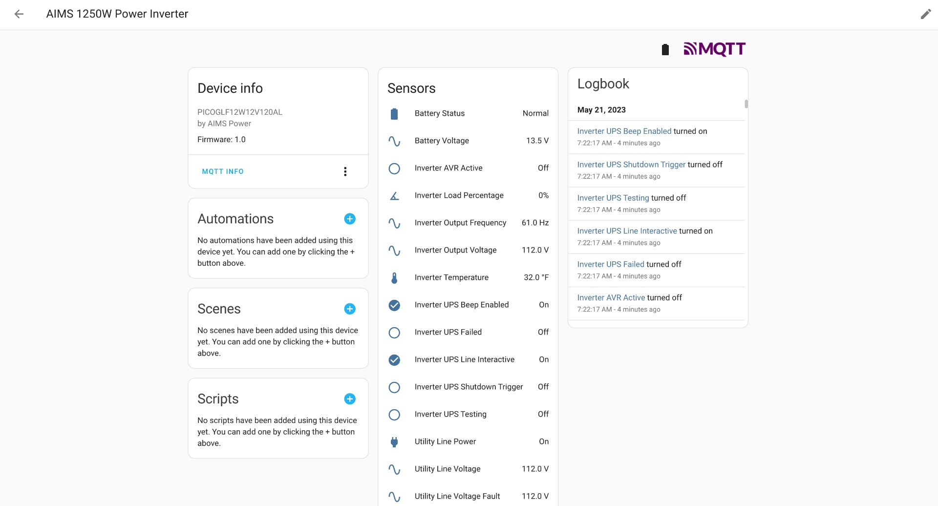
The following data will be available in Home Assistant via an auto-discovered MQTT device once this app is fully setup and configured according to the instructions below:
- Battery Status (OK/Low)
- Battery Voltage (Volts)
- Utility Power Active (Yes/No)
- Utility Line Voltage (Volts)
- Utility Line Voltage Fault Level (Volts)
- Inverter Load Percentage (%)
- Inverter Output Voltage (Volts)
- Inverter Output Frequency (Hz)
- Inverter Temperature (c)*
- Inverter UPS Failed (Yes/No)
- Inverter UPS Testing (Yes/No)
- Inverter UPS Shutdown Flag (Yes/No)
- Inverter UPS Beep Enabled (Yes/No)
- Inverter UPS Line Interactive Mode (Yes/No)
- Inverter UPS AVR Active*
* not applicable for PICOGLF12W12V120AL
The Quest to Automate Equipment Shutdowns
An AIMS power inverter combined with a large marine battery is a great way build your own UPS/battery backup that has significantly more capacity than your average APC, Tripp Lite, or CyberPower retail models to protect your home gear. The only problem is unlike packaged commercial UPS products, there is not an easy way to monitor battery health during a power outage to know when the battery is running low. This is a useful feature of commercial products that can allow you to safely power down your equipment before the battery is depleted to avoid data integrity problems.
After a long power outage and sudden power loss caused by an empty battery created problems with my gear, I was determined to find a solution to monitor the status of my custom UPS system so everything could shut down gracefully before the battery was fully depleted. After much googling, I found the RJ45 pin-out and serial protocol for an AIMS power inverter on the Solar, Wind, and Battery Systems forum. This was for a different model than what I own, but I figured it was worth exploring.
Proof of Concept
Using a USB serial port adapter and an old patch cable that was cut up and wired according to the AIMS Power specifications it worked! I simply typed in Q1,hit Enter and the inverter returned:
(111.0 111.0 112.0 000 60.0 13.5 00.0 00001001
After reviewing the protocol spec sheet again, I could see everything I needed was there and more in a very specific format I could easily parse programmatically:
 (MMM.M NNN.N PPP.P QQQ RR.R S.SS TT.T b7b6b5b4b3b2b1b0<cr>
The meaning of each field is list as followed:
Start byte : (
I/P voltage: MMM.M (M is an integer number ranging from 0 to 9. The unit is Volt)
I/P fault voltage : NNN.N (N is an integer number ranging from 0 to 9. The unit is Volt)
O/P voltage : PPP.P (P is an integer number ranging form 0 to 9. The unit is Volt)
O/P current : QQQ (QQQ is a percentage of maximum current, not an absolute value)
O/P frequency : RR.R (R is an integer number ranging from 0 to 9. The unit is Hz)
Battery voltage : SS.S or S.SS
 S is an integer number ranging from 0 to 9. For on-line units battery voltage/cell is provided
 in the form S.SS. For standby units actual battery voltage is provided in the form SS.S. UPS
 type in UPS status will determine which reading was obtained.
Temperature : TT.T (T is an integer number ranging form 0 to 9. The unit is degree celsius)
UPS Status : <U>

 <U> is one byte of binary information such as <b7b6b5b4b3b2b1b0>. Where bn is a
 ASCII character ‘0’ or ‘1’.
 UPS status :
  Bit Description
  7 1 : Utility Fail (Immediate)
  6 1 : Battery Low
  5 1 : AVR 0: NORMAL
  4 1 : UPS Failed
  3 1 : UPS Type is Line-Interactive (0 is On_line)
  2 1 : Test in Progress
  1 1 : Shutdown Active
  0 1 : Beeper On
Time to Build
Now that I knew how to get data out of the AIMS Power inverter via the RJ-45 interface serial port, I decided to build the automated solution using a Raspberry Pi Zero W since it is a cheap device that has a both Wi-Fi which is required to talk to my Home Assistant MQTT server and a hardware UART/serial controller with designated pins that would make talking to the AIMS Power inverter easy using Python. The only catch I needed to solve for was a voltage problem between the Raspberry Pi operates at 3.3 volts and the inverter serial port operates at 5 volts. Connecting the 5v inverter serial port to the Raspberry Pi directly would fry the pi so a bi-directional multi-channel logic level converter is required between the devices (see required hardware below) so they play nice together.
Required Hardware & Software
- Compatible AIMS Power Inverter (what I purchased and I know works PICOGLF12W12V120AL)
- Raspberry Pi Zero W or other version of Raspberry Pi
- Spare RJ-45 ethernet cord you don't mind destroying to make your custom cable
- At least a two channel 3.3V-5V Logic Level Converter (Anmbest 4 channel on Amazon is what I used)
- Soldering Iron to solder on pin headers.
- Existing Home Assistant install with MQTT configured.
Links to products may be affiliate links that may pay me a commission.
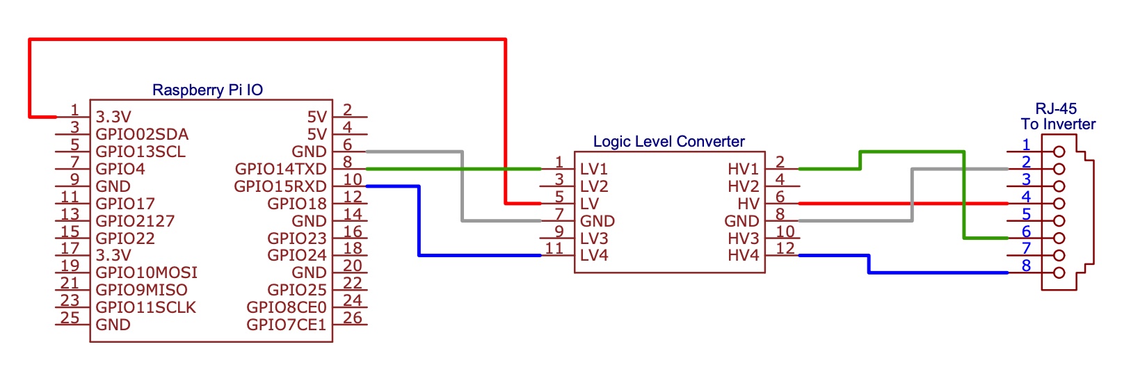
Hardware Build Instructions
Below you will find the schematic to wire up the Raspberry Pi to the 3.3v to 5v logic level converter and then to the RJ-45 module that wil be inserted into the side of the AIMS power inverter. The Raspberry Pi pins should work on any modern raspberry pi with a 40 pin header. I chose to solder a pin header to both the logic level converter and the Raspberry Pi Zero W so I could use standard Dupont cable connectors on the pins. Alternatively, you can solder the wires directly to the contacts on the boards.
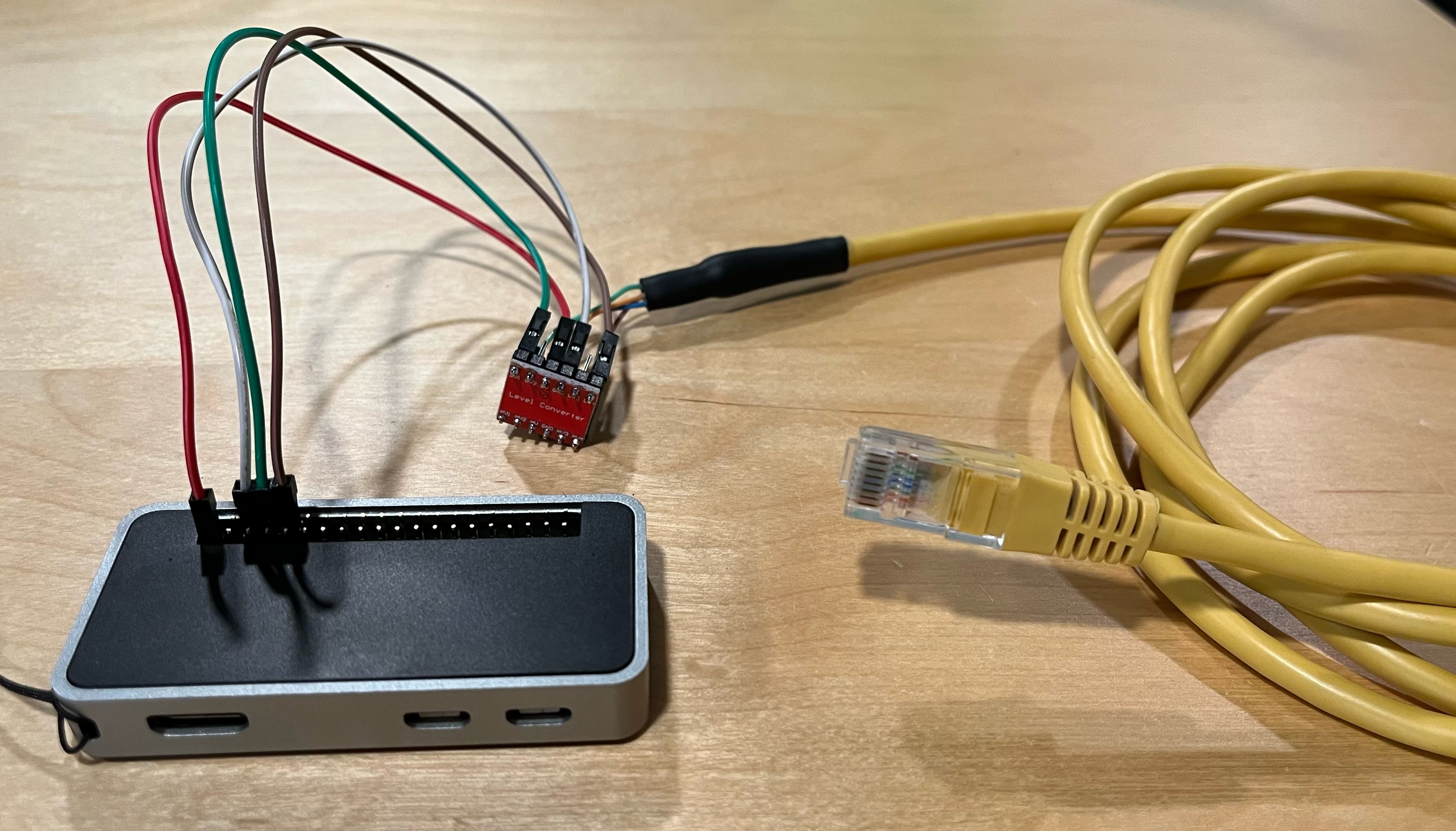
A picture of the finished circuit (pay no attention to the color of the wires as they do not match the schematic).
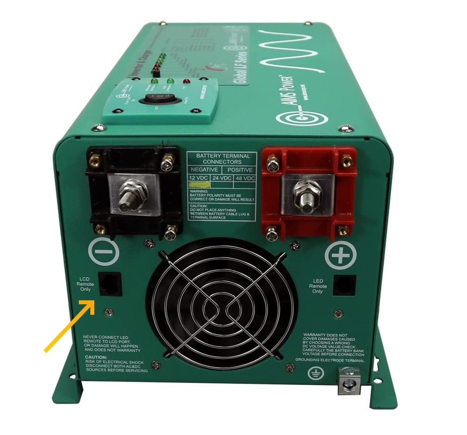
Plug your custom cable into the RJ-45 jack that is labeled LCD Remote Only:
This was built using the specifications found on the Solar, Wind, and Battery Systems forum. Backup reference copies have been included in this repo:
Software Installation & Configuration
Configure the Raspberry Pi Zero W
Some prep work is needed to disable bluetooth so the UART controller can be fully utilized on the Raspberry Pi Zero W and potentially other Raspberry Pi models. These instructions will assume you already have a fully configured and updated Raspberry Pi Zero W that you can SSH into.
- Run the following commands on your Pi Zero W:
sudo systemctl disable hciuart.service
sudo systemctl disable bluetooth.service
- Edit
/boot/config.txtand add the following lines at the end of the file:
dtoverlay=disable-bt
enable_uart=1
- Reboot the Pi Zero W.
When the system is back up, make sure /dev/serial0 is mapped to ttyAMA0 by running ls -l /dev/serial* as shown below:
ls -l /dev/serial*
lrwxrwxrwx 1 root root 7 Apr 30 21:03 /dev/serial0 -> ttyAMA0   < Good
lrwxrwxrwx 1 root root 5 Apr 30 21:03 /dev/serial1 -> ttyS0
Core Software Installation & Configuration
Run the following commands (ignoring the comments) to install the necessary dependencies and core app from the GitHub repository.
# Install system dependencies
sudo apt-get install python3 python3-pip git

# Move to /opt directory
cd /opt

# Clone the repository which will copy the app to /opt/AIMSPowerInverterMQTT
sudo git clone https://github.com/stevesinchak/AIMSPowerInverterMQTT.git

# Move to the /opt/AIMSPowerInverterMQTT directory
cd /opt/AIMSPowerInverterMQTT

# Install Python dependencies
pip3 install -r requirements.txt
Now it is time to fill in the config.yaml file with the specifics for your install. Edit the file with sudo nano /opt/AIMSPowerInverterMQTT/config.yaml and set the IP address of your MQTT Home Assistant host and the proper user/pass for authentication and save the file with Control + O followed by Enter and you can exit the editor with Control + X.
#This is the correct port for a Raspberry Pi Zero W but may need to be updated if using a different device
serialPort: /dev/ttyAMA0

mqttHost: 0.0.0.0
mqttPort: 1883

mqttUser: user
mqttPass: password

expireAfter: 600
baseTopic: AimsPower

#Customize the following for your specific model but be careful not to alter the JSON formatting
modelTopic: Aims1250PowerInverter
deviceDetailsJSON: '{"identifiers": "Aims1250PowerInverter", "manufacturer": "AIMS Power", "model": "PICOGLF12W12V120AL", "name": "AIMS 1250W Power Inverter", "sw_version": "1.0"}'
Validation Testing
Before proceeding, let's make sure everything was configured and is running properly. Simply run python3 /opt/AIMSPowerInverterMQTT/GetInverterData.py from any path and verify there are no exceptions or errors and that you see your inverter device being auto-discovered in Home Assistant. If you are having problems, make sure your info in the config.yaml is set properly and you can also use the included SerialTest.py script to validate the serial port aspect of the app alone by running python3 /opt/AIMSPowerInverterMQTT/SerialTest.py.
Scheduling with Cron
We will use Cron to automatically run the Python app every few minutes to capture new data from the inverter and send it to Home Assistant. Cron is usually automatically installed on Raspbian but you can make sure by running the following:
sudo apt-get install cron
sudo systemctl enable cron
Next, let's configure Cron to run our app every two minutes. Get started by typing in crontab -e and hit enter. If this is the first time you are running crontab, you will be asked to select an editor (I suggest option 1 which is nano). Add the following to the bottom of your crontab file to make it run every two minutes:
*/2 * * * * python3 /opt/AIMSPowerInverterMQTT/GetInverterData.py
If you would like to run your job at a different interval, check out the crontab guru examples site. Remember to hit control + O to save and control + x to quit.
Cron jobs will run silently in the background, but to help with monitoring this app logs to syslog as well so you can monitor this app by running tail -f /var/log/syslog on most systems.
Building an Automation in Home Assistant
Now that we have data flowing to Home Assistant every two minutes, it is very easy to create an automation to send you a notification or call other services to power down electronics or more. On the main device page, just hit the plus icon in the "Automations" section to start building your first automation with this device. Please refer to the official Home Assistant documentation for building an automation and integrating devices.
Contribute
If you have ideas for improvements, requests, issues, or would like to contribute code, please open a issue or create a pull request in our github repo at https://github.com/stevesinchak/AIMSPowerInverterMQTT/.